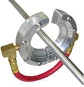
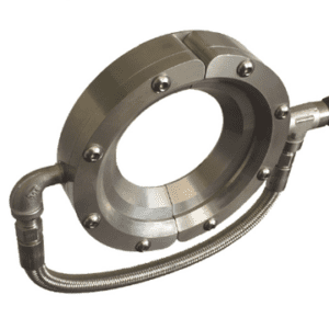
 The Gate Air Wipe is a 2 piece hinged Air Amplifier that provides a high volume circle of high velocity compressed air. Gate Air Wipes amplify air at a 25:1 ratio, minimizing the amount of compressed air usage from items such as drill pipes and other home made designs. Gate Air Wipes have an open and shut design that allows for easy placement of products and movement.
Gate Air Wipes are available in aluminum and stainless steel and come in 1″ (25mm), 2″ (51mm), 3″ (76 mm), 5″ (127mm), 7″ (178mm)
Gate Air Wipes Products
-

Gate Air Wipes
$231.00 – $2,299.00 Select options This product has multiple variants. The options may be chosen on the product page
INDUSTRIAL SOLUTIONS FOR GATE AIR WIPES
USES FOR AIRTX GATE AIR WIPES
• Blow-off chips, trim scrap, water, dust
• Part cleaning before finishing, replacing open air lines
• Cooling Molded parts and castings
• Continuous length products, like hose, pipes
AIRTX GATE AIR WIPES ADVANTAGES
• Low cost
• 25:1 air amplification ratio
• No maintenance, no moving parts
• Easy to control flow/force
• Greatly reduced noise
• No electricity or explosion hazard
• Instant on/off
• Easy placement of products with The Gate like open and shut operation
Technical Data For Gate Air Wipes

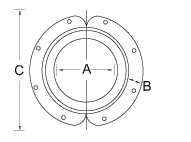
| Gate Air Amplifier Dimensions | |||||
| SS Model # | AL Model # | A | B | C | Inlet |
| 16101 | 1″ | 1″ | 3″ | 1/8″NPT | |
| 25mm | 25mm | 76mm | |||
| 16102 | 2″ | 1″ | 4″ | 1/8″NPT | |
| 50mm | 25mm | 76mm | |||
| 10103 | 16103 | 3″ | 1.5″ | 6″ | 1/4″NPT |
| 76mm | 38mm | 152mm | |||
| 10105 | 16105 | 5″ | 1.5″ | 8″ | 1/4″NPT |
| 127mm | 38mm | 203mm | |||
| 10107 | 16107 | 7″ | 1.5″ | 10″ | 1/4″NPT |
| 178mm | 38mm | 254mm | |||
| Gate Air Amplifier Performance Chart (.002 shim) | ||||||
| SS Model # | AL Model # | CFM Usage | ||||
| 20psi | 40psi | 60psi | 80psi | 100psi | ||
| 16101 | 8 | 12 | 16 | 20 | 26 | |
| 16102 | 14 | 18 | 22 | 26 | 30 | |
| 10103 | 16103 | 18 | 24 | 28 | 32 | 38 |
| 10105 | 16105 | 28 | 38 | 48 | 54 | 62 |
| 10107 | 16107 | 38 | 56 | 70 | 80 | 90 |
GENERAL INFORMATION ON NOISE IN THE WORKPLACE
| Sound Level | Application | Recommended NIOSH Tolerance (w/o ear protection) | |
| 110 | 1/2″ Open Pipe | 30 min. | |
| 105 | 3/8″ Open Pipe | 1 hr. | |
| 102 | 1/4″ Copper Tube | 90 min. | |
| 92 | 6 hrs. | ||
| 90 | 8 hrs. | ||
| 85 | Targeted sound levels for most manufacturing facilities | ||
| 60 | Normal conversation – An increase or decrease of 10% in sound levels makes a substantial difference in the ear damaging effects of noise | ||
WANT TO KNOW HOW MUCH AIR YOU ARE USING?
Compressed air discharge to atmosphere through sharp, square edged orifice and sea level cfm.
| Compressed Air Flow Through Orifice Chart – Orifice Diameter in Inches | |||||||||||||||||
| psi | 1/64 | 1/32 | 3/64 | 1/16 | 5/64 | 3/32 | 7/64 | 1/8 | 5/32 | 3/16 | 7/62 | 1/4 | 5/16 | 3/8 | 1/2 | 3/4 | 1 |
| 20 | 0.12 | 0.49 | 1.07 | 1.9 | 2.97 | 4.28 | 5.84 | 7.59 | 11.8 | 17 | 23.1 | 30.4 | 47.2 | 68.6 | 122 | 269 | 468 |
| 30 | 0.15 | 0.63 | 1.39 | 2.47 | 3.87 | 5.58 | 7.6 | 9.89 | 15.4 | 22.2 | 30.4 | 39.6 | 61.5 | 89.4 | 158 | 350 | 634 |
| 40 | 0.19 | 0.78 | 1.72 | 3.05 | 4.77 | 6.08 | 9.38 | 12.2 | 19 | 27.3 | 37.5 | 48.8 | 75.8 | 110 | 195 | 432 | 781 |
| 50 | 0.23 | 0.92 | 2.04 | 3.62 | 5.67 | 8.17 | 11.1 | 14.5 | 22.6 | 32.5 | 44.6 | 57 | 90.1 | 131 | 232 | 513 | 929 |
| 60 | 0.26 | 1.07 | 2.37 | 4.2 | 6.57 | 9.46 | 12.9 | 16.8 | 26.2 | 37.7 | 51.6 | 67.2 | 104 | 152 | 269 | 595 | 1075 |
| 70 | 0.3 | 1.21 | 2.69 | 4.77 | 7.47 | 10.8 | 14.7 | 19.1 | 29.7 | 42.8 | 58.8 | 76.4 | 119 | 173 | 306 | 676 | 1223 |
| 80 | 0.33 | 1.37 | 3.02 | 5.35 | 8.37 | 12.1 | 16.5 | 21.4 | 33.3 | 48 | 65.8 | 85.6 | 133 | 193 | 343 | 757 | 1371 |
| 90 | 0.37 | 1.52 | 3.37 | 5.92 | 9.27 | 13.4 | 18.2 | 23.7 | 36.9 | 53.2 | 72.9 | 94.8 | 148 | 214 | 379 | 839 | 1518 |
| 100 | 0.41 | 1.66 | 3.66 | 6.5 | 10.2 | 14.7 | 20 | 26 | 40.5 | 58.3 | 80 | 105 | 162 | 235 | 416 | 920 | 1664 |
